Product information
- Easy integration of the station into existing lubricant supplying systems
- Easy connection to new production plants
- Continuous monitoring of the medium for air inclusions and discharge of medium, independent of air bubble detection
- Detects the smallest air bubbles from dia. 1.3 mm and discharges them
- Monitoring of size and number of air bubbles
- Lowest loss of medium, since only the part of the medium that contains air bubbles is discharged
- Integrated medium storage for an uninterrupted supply, also during the discharge process and when changing containers
- Monitoring of process variables with threshold value definition and reporting of threshold value violations
- 3 freely configurable 24 VDC digital alarm outputs for window and individual comparisons of different process values
- Easy and intuitive operation
- Operating and parametering directly via the operating screen (HMI) or with remote control via bus system or DIO's
- Harting plug with integrated bus and pneumatic connection
- Ethernet bus with MODBUS TCP protocol: read out and write alarm values, read out the status of the alarm outputs and read out current values of the process values
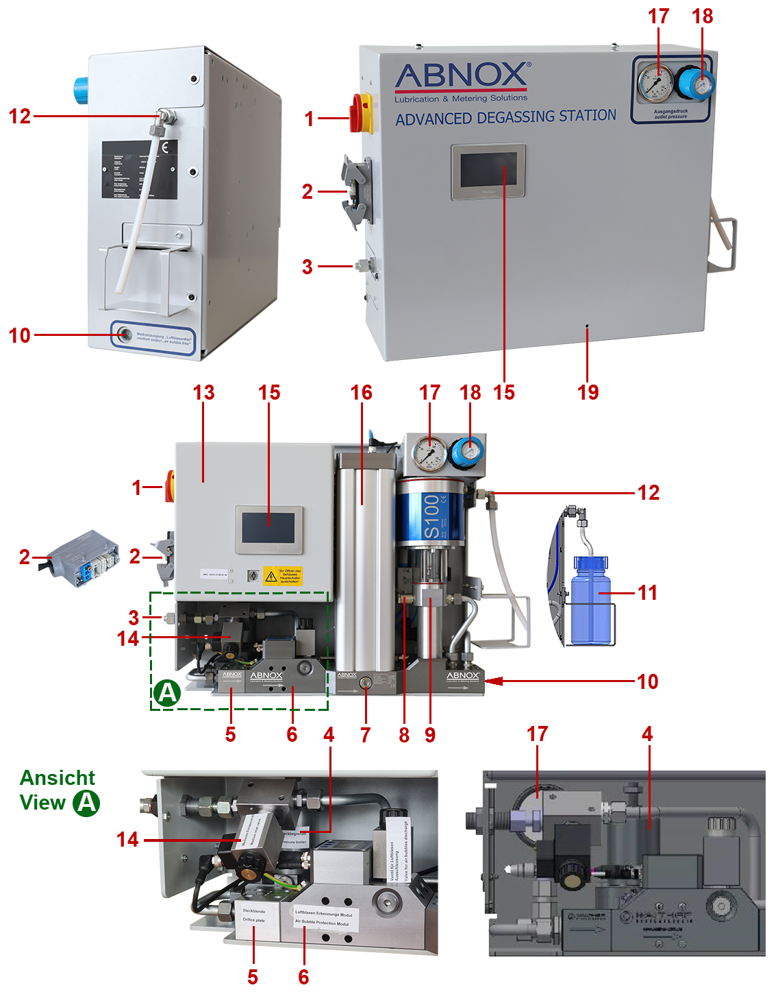
- Electrical main switch (ON/OFF power supply)
- Electric/pneumatic interface (HARTING plug)
- Hydraulic input (medium inlet), pipe connection with cutting ring 12L 24°
- Material pressure regulator MDR
- Plug-in cube SB
- Air Bubble Protection System ABPS
- Bursting disk (> 10.5 bar pressure and medium are discharged through the relief opening)
- Air release valve (pressure relief/exchange cycle)
- Booster pump BP
- Hydraulic output (medium outlet) 1/2“ BSP
- Collecting container/Wide-neck bottle, LDPE (1,000 ml) discharged medium (available as accessories)
- Output pressure relief (pressure and medium which is contaminated with air bubbles)
- Control box
- Main valve supply medium (screw-in seat valve)
- Operating screen HMI (Human Machine Interface)
- Medium reservoir GC (grease container) without air bubbles
- Pressure gauge outlet pressure (0 - 160 bar)
- Pressure regulator hydraulic outlet pressure
- Leakage boring for medium discharge
Highly viscous medium flows into the station through medium inlet (3). A pressure controller reduces the inlet pressure of the medium to a lower level in order to increase the size of the air bubbles. The orifice plate (5) is mounted behind the material pressure regulator MDR (4) and will reduce the volume flow to such an extent that any existing air bubbles will be correctly detected and identified in the adjacent Air Bubble Protection System (6). This module monitors several process values and can discharge medium which is contaminated with air bubbles (12). Parallel to that, a pressure-controlled Grease Container GC (16) is installed where the gas-free medium can be temporarily stored. The Module Grease Container (16) will guarantee a continuous discharge of medium, also during an outward transfer process. A Booster Pump BP (9) is installed at the end of the line system; this is an adjustable high-performance pump. It will re-adjust the outlet pressure of the medium – depending on the individual setting – back to the original value. Then the outlet pressure will match the inlet pressure of the medium again, or be higher, up to max. 250 bar.
Modes of operation
manually, automatically / local and remote
Input medium specification
Lubricants up to NLGI 3 / 1'000'000 mPa.s non-aggressive mediums/fluids, particle size < 150 μm
Max. Volumeflow (shortterm) [cm3/min]
1500
Max. average volumetric flow [cm3/min]
100
Min. / max. Fillingvolume mediumstorage GC [cm3]
40 / 2000
Min. / max. workingpressure medium inlet [bar]
20 / 150
Min. / max. workingpressure medium outlet [bar]
0 / 250
Connection medium inlet external thread
Pipe connection with cutting ring 12L 24°
Connection medium outlet internal thread
1/2'' BSP
Compressed air quality
ISO 8573-1:2020 [6:4:4]
Minimum detectable airbubbles [mm]
dia. 1.3
Min. / max. pneumatic operating pressure [bar]
4 / 10
Interface
DIO 24 [VDC] / HMI 4,3“/ ModbusTCP
Max. back-upfuse [A]
16
Nominalcurrent [A]
5
Freely definable alarm outputs [V DC]
3 x 24
Voltage [V AC]
110 / 230
Protectionclass
IP 66
Min. / max. operatingtemperature [°C]
4 / 10
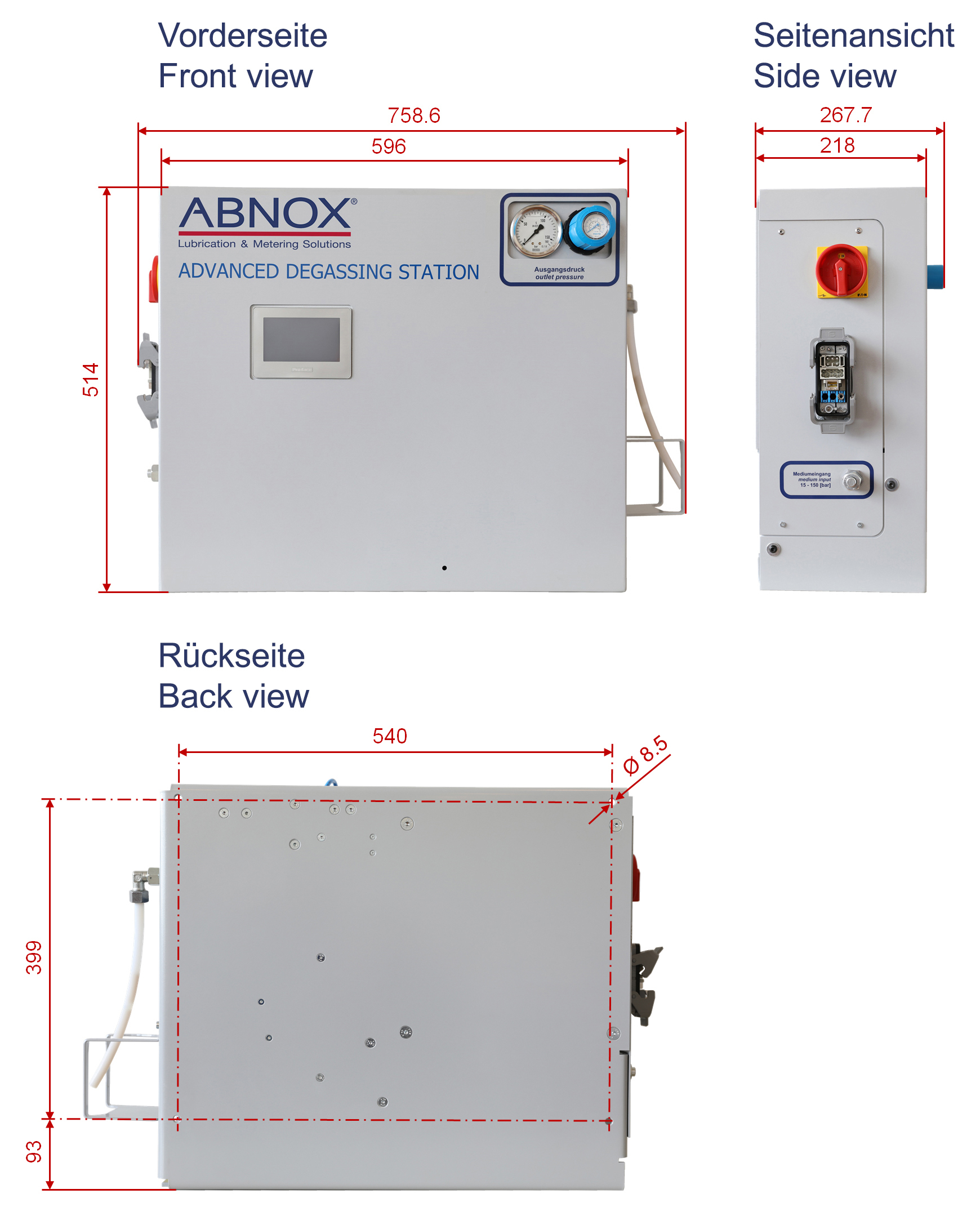
Dimensions L x W x H [mm]
759 x 268 x 514
Weight [kg]
18